iPhone 7 Plus Sound & Front Camera Not Working By iTechRepairs
You hi everyone there will be a video about an iPhone 7 plus that has the classic audio IC or audio codec problem. This one also has a problem with the front camera not working when you switch to the front camera, it's just a black screen I'm, not to sure. If the problem is related to the audio codec, not working as in when the phone was dropped, it something else fail or not. I'm going to fix. First, the sound I see problem, and then I'm going to start checking on the camera, with maybe a new flex cable or see if it's a loose connection or whatever the case may be you're, also going to see in this video a technique that I've seen myself on the internet a couple of years ago, when I was doing the iPhone 5 charging ICS, but back then I couldn't practice a lot on that technique, because the tools that I had weren't as powerful, but now I have this quick setup that I've showed you in the presentation, video, and now I can actually use this technique. Also, since we're always replacing the ICS I couldn't care less if TAC just gets burned.
What that technique does. Is it allows you to easily remove the IC without you having to heat up the board twice? Also, what I will show you in this video is another jumper that we make on the on this problem. So, generally speaking, you run one jumper and the problem is sorted, but we have maybe one or two phones that came back right, and we discovered that and the meet the IC. You have to point to ground points and those points tend to break as well. So the same as we do on the base band video we're going to run the jumpers there, as well as the classic jumper, to avoid the phone coming back, and we haven't to work twice, and the customer obviously has to come back and forth and that's not a pleasant situation for anybody.
How do you identify that? It is the sound problem, the sound code or the audio I see problem well. First, the customer calls you and tells you that nobody can I can hear them when they switch the speaker. It defaults back to the earpiece, and obviously they can't hear anything. People can't hear them so on and so forth. Second, when the phone arrives in your shop, you go into the voice memos app, let's see, and you'll, see here now that the recording button is grayed out.
Okay, that's another giveaway that the problem is that and then the third one, but I'm not gonna. Do it now, because it's going to take forever before the phone boots up it's as I said, the phone takes 5 10 15 minutes whatever it wants to fully turn on. So you will be stuck on the Apple logo. The home button will might will click, the phone will vibrate, but the phone won't finish booting up for a very, very long period of time. So what I'm going to do now is I'm going to strip apart phone, and we're going to continue the video with the board view.
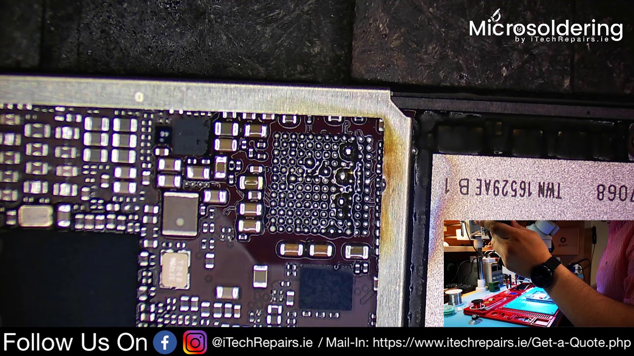
Okay, so now that we remove the board we're going to peel the tape first, and then we'll remove the audio codec I'm using hot air to peel off the tape, because I plan on reusing it and I want to put captain tape I'm trying to keep the looks as Spock as possible. It was that easy. We have to remove the audio codec I'm, going to wake on the quick to a 3G to warm up, and you want to see how easy it is, but this method is going to apply the flux first, on the around the OIC, there were a few comments in the previous videos that all the job is messy or whatever we always clean the board after we finish with the ultrasonic cleaner. So nothing that you see during the process is going to be left on the board once the repair is finished, so bear that in mind as well before you start commenting. What you do is you'll play a bubble, or you make a blob of solder and then you'll hold it on the actual IC itself.
Let's see it now, it's very, very there! That's how easy it is. This is what wasn't that from there on the see that blah blah it's older than I've used now, what I do is I'm gonna wick this with the whole surface, Ernie weenie, money mo, which one did I use. I'm going to use the delivery. I got like two or three pieces. You want to make sure that you have enough clocks, because otherwise it's not going to stick to the wick, and again I know it looks messy, but at the very end, after the whole repair is going to be finished.
We are going to clean the board in the ultrasound machine. So it's it doesn't matter how it looks now. Okay, now we turn the board just a little, so we can finish up holder. Okay, that's that for now a question that I get asked a lot when doing these videos in the comments section is well. How do you know that? That's the problem? How do you identify that? That's the problem and so on and so forth? How do you know that? That's the jumper that you need to run well, it's very simple: I've done my research I'm, not claiming that I'm the first one to discover these things.
A lot of these repairs online you'll see there are either discovered by just a Jones. Our channel is iPad. We have, or you'll see them on Rivas web website, or we are YouTube page, that's our AWA! This is just me showing you how I do it? It's not me claiming that I've invented this repair, and this is, you know me demonstrating that I'm the best never claimed that I'm the best, but at what I'm doing, and I think I'm, quite okay I'm not going to go any further in today. So what we do now is we uncover the main trace that gets broken as just demonstrated in one of her videos. This whole line here on the left and on the right of the same tray or on the nanoohm, depending on how you're looking at if it's known as a fault line, because that's the weakest point of the board itself, that's where things are likely to break.
That's why you get all these errors, even with the base band and whatnot. We've had other phones where we've had these traces broken because again, that's fault line regardless. We've still done this jumper here as well. These jumpers too, and what I was telling you about the ground points. So these are the two ground points, the two that we've seen to break as well, so this and this okay.
So what we do is we scrape the paint just here, and then we run a jumper across and that way the phone doesn't come back now if it has other hidden, broken traces. Underneath that you don't see, that's a different question, but so far they didn't have problems. Just by doing these. These two jumpers here it is very, very hot. In Ireland, over the last two weeks, I've been roasting.
It here in the shop and even now, it's a pain to make these videos, because I had to clone to close the windows so that you don't get any background noise, so I hope you can appreciate that. Okay, so you want to scrape until it's all shiny, because otherwise you won't get a proper solder point. There it'll be just on the surface, and you don't want that. Also, when you make these jumpers, you want to make sure that doesn't they're as flat as possible, because otherwise the icing is going to sit crooked, and you're going to need to use more temperature than then you have to get the new IC to sit down in its correct position, and now I'm just telling the exposed traces there like so now for the jumpers. I have a point: zero, two millimeter wire, but my favorite is the point: zero six millimeter wire.
It seems to last longer and to hold better yes. I know it is thicker, and it may be harder to work with, but in the long run for me at least it is worth it now. Hopefully, this one happened, but if it does, that's not a problem. You'll see, sometimes when you, when you put the wire there, and you use the heat on the pad on this pad here, it has a tendency to come off. If it's.
If it is broken, if it doesn't come up yeah it did, but when it doesn't, it makes your job easier. If it does, it's okay, but you still you'll, have to make a small circle with the wire at least that's the way I. Do it anyway, so keep on going back and forth with the wire, because I want to make sure that it is properly soldered I, don't want it to be half my solder. Remember that the first job, the phone this stops working again. That's why I keep ongoing playing with it.
The wire that I'm used has enamel on it. So it does take a little of heat for that enamel to dissolve to go away so that the solar can adhere to it. And now we try to make that curl there just a little curl, so that was complete and it sort of simulates a pad. Even if you do a straight wire, it's still fine, but it's just that's that's my style of doing it. You don't necessarily need to copy me, use your own judgment, man, it's so hot, okay, I'm, just going to clean the surface.
Just a little to make sure that the jumper is sitting in the place mmm-hmm, and now we're on the second jumper for Diem for the ground point like, so now we break the wire yeah again you want to make sure that you clean it as good as you can at this moment, because you're going to use the UV masked to secure the wire and make sure that it's not moving at all, but before you do that what I always like to do is I go with a bit of hot air. On those jumpers, you see it even moved a little. That's fine, and then you're going to pry it back. So in that mask again, the main reason for using UV mask is to just hold the wire in place when, when you expelled me, oh I, see so actually, when the IC moves into its place, you don't run the risk of the wire actually moving from the D from the initial position that you put it, you don't need to apply a lot of it either. Just can you get it in there, and then you leave it for probably about a minute to cure.
In the meantime, take the box, here's a piece of advice, always inspect your eye sees before soldering them, because I've had surprise bad surprises when I see that were supposed to be brand new had also all sorts of gunk underneath them. So this one as you can see, it is brand new, so shiny all clean okay, but that's not what I'm talking about I'm talking about the other side. So, as you can see here, the EIC is very, very clean. That's that's good to go on the board without having to do any more training or anything like that. I'm going to set it aside for the moment.
Yeah, do your math is cured when you use this small UV lamp, it doesn't take forever to cure. The area is to use big UV lamps and those Jesus Christ you're, like you, would leave the board in there for half an hour and still wouldn't be done so obviously apply a bit of flux, make sure it's well spread, and even okay. Now, as a precautionary measure, although I do have the temperature set down to a tee I'm still going to use some coins, these are just 50, Cent's, one-year or whatever they have the heat spread. Like you, don't cook the nail, you don't cook the CPU or the page band. You know just preventative measures that you have the correct position: I, don't want it to be exactly perfect, and it's position.
I wanted to wiggle a little or to move when you use the heat, I'm going to put it just slightly, slightly off something like this. It gives me enough indication if it moves or not, and then we go with the hot air. You see that the flux has dried up. You go in put a bit more because these new I see is that they I don't think they have low milk underneath, and they have something some different composition there. So the AC is in its place, we're going to let the board cool off a bit I'm not going to stop the video, because I want you to see that it is the steps that I do before.
I power on the phone, so, as I was saying, with these new I see the composition of the solder: it's not low melt, so they don't really melt as quick as if you were to do a Reno. So that's why they tend to suck the flux a lot and they then you need to apply a bit more or a bit more. You know whatever the case may be, and because it's not low melt, I, always inspect the bore from the side to see if the chip is actually sitting down. As you can see there, the balls are nice and flat underneath the IC. So what that means to me is that the phone is good to run the first trial and see if it actually works.
You're not gonna, get the screen, and I'm also going to connect the front camera just for fun to see if it actually works now or not again, I don't think it's anything. I know it has ain't nothing to do with the sound I see failing goosing, it's not a problem. That's related to the sound I see with the front camera, not working, but if something got dislodged or move out of its place by reconnecting, the cable should be fine. Turning on the power supply, the shape of one and then two so the founders, even the stern on, let's see if it is the repair was okay or not, depending on how long it takes to boot, and then we're going to the settings. Okay, no seam for install, that's fine, no voice memos.
And what do you know the button is red? If you press it, it's going to record what is going to record nothing because it doesn't have the microphone connected. That was me going over the proximity sensor, so that works and that's okay. Now, let's see if the camera works, let's try again, okay, going to pause the video for now, because I need to find a flex, cable, I'm, going to come back, and we'll see how that problem can be sorted as well. I managed to find a flex cable from a screen assembly that I have here. Let's see what happens see by replacing the flex cable, really camera working again Donna.
If it doesn't, then we have to go back to the drawing board and see what the problem may be. Okay, so the front camera still doesn't work I, wonder because is it not working because the rear cameras aren't connected? Okay, let's check that as well, and now I can actually use the battery itself rather than the power supply. No Stigmatic. Okay, I'll have a quick look through that X dub and see if I can find anything, and then I'm going to come back and show you what I've discovered. So it turns out that it was pretty easy actually upon closer inspection.
This resistor here this one here wasn't actually properly soldered on to the board um. So sorry for not showing you that but yeah that's. How is it being this resistor here it had a bit of this black under fill over it silicon, whatever the hell. This thing is- and it was just sitting on this- it wasn't soldered on to the board itself and so just to show that it is working again not to mention that that PW doesn't have this particular board model, or it does have it, but it has no no schematics for it. It's just a generic board view there.
That's the front camera working okay, so now the phone is cleaned is fully assembled, and we're going to run the final test just to make sure that everything is fine. It's not a repair that takes a very long time. It's not a repair, that's very difficult! If you have experience with micro solving what you need to make sure that you take your time if you're doing it for the first time for the second time or whatever the case may be, and if you're comfortable enough to just jump in straightaway and do the world repair very quick, well, happy days, and I'm very happy for you, but I would take my time if it's your first time doing it. So the first problem was the sound problem. Okay, now the button is red and if we hit record, it is going to record, and it'll have absolutely no more problems.
Okay and the second problem was the camera, the front camera. Okay, so the rear camera still works, and then we have camera which is working now. Okay, the front camera was very easy and, as I showed you in the video, it was just a tiny resistor that was there wasn't. Actually soldered in place was just sitting with black under filter. We resolved that the resistor and now everything is, is happy days.
So thank you very much for watching, and I'll see you in the next video.
Source : iTechRepairs
Phones In This Article

Related Articles


![GALAXY NOTE 20 ULTRA | Advanced TIPS & TRICKS, Best Features Explained [#1/3]](https://img.youtube.com/vi/TCHesZCtPEo/maxresdefault.jpg )


Comments are disabled
Latest Articles